Water Energy Reclamation for Process Facilities
An effective way to reclaim energy and reuse gray water derives from a process that uses elevated water temperatures for a research application. The control sequence for monitoring is highlighted.
Facility owners are striving to make their building systems as energy efficient as possible and a process derived from a research application may help. Improving energy efficiency reduces operating costs and delivers a positive impact on the environment and carbon footprint. The perception regarding process and/or research systems often is there are no opportunities to design a system that can save energy relative to the baseline needed for a specific research application.
For some process water systems that use a large volume of water and a significant amount of energy to add heat, facility managers can reclaim the energy from the process and in some cases, even reclaim the effluent itself.
There is an effective way to reclaim energy and reuse gray water (clean or partially clean wastewater after a process) from a process that uses elevated water temperatures for a research application. In addition to being placed back into the process water system, the heat can also be distributed to other hot water systems in the building. Where the specific application permits, the gray water is reclaimed and reused in the process research water loop.
Wastewater heat, water reclamation
Typically, gray water from the research application is sent to sewer after being cooled to below 140 °F. A process research application that uses significant energy and large volumes of water presents a great opportunity for the designer to create a process to return significant resources back into the building systems. The concept is most applicable for systems heating water in the 160 to 200 °F range.
After hot process water is used for the research application, the gray water can be drained to a collection sump or insulated tank rather than being sent to the sewer. As the water is collected, assuming sufficient incoming flow, the float will activate and start the process of reclaiming the energy. The water is pumped through the system where the process of reclaiming the energy and water occurs.
The first stage downstream of the pump is a “water to water” heat exchanger where approximately 180 °F effluent heat is exchanged indirectly with the building potable hot water system, other heating hot water systems in the building, or the process loop makeup. Multiple heat exchangers can be arranged in a series depending on priority and expected usage. The gray water is routed back to the process water loop make-up to be reused for process research. Since the water temperature is elevated even after the heat exchanger, the remaining heat energy is returned to the process loop.
Locating the water-to-water heat exchanger in the first position downstream of the pump ensures the maximum reclaim efficiency. When the research processes go inactive for a period and hot water is no longer needed for that application, reclaimed energy can still be directed to the other hot water needs in the building.
When there is not enough load on the reclaim system, the water is cooled and ejected to the sewer. The temperature is monitored to verify it is less than 140 °F before being drained/pumped to the sanitary sewer. If the effluent temperature is greater than 140 °F, a heat exchanger reduces water temperature prior to release to sanitary sewer. A diagram of the process is highlighted below:
 Diagram 1: A custom sequence of operations must be developed and implemented to control and monitor this process. Courtesy: McClure Engineering
Control sequence for monitoring
For this system to work efficiently, a custom sequence of operations must be developed and implemented to control and monitor this process. The following is a sample summary of a sequence of operations for this process:
- The water from the process is drained to a sump where the pumps (see diagram 1, “P-1” and “P-2”) are energized when the water level activates the float in the sump. The water is then pumped through the system.
- When the process grey water from the sump is greater than 140 °F for more than 15 minutes, the control valve (see in Diagram 1, label “CV-1”) opens to enable the heat exchanger (for building potable water, Diagram 1, “HX-1). The control valve remains open if the temperature of the grey supply water is 140F or greater.
- After the gray water passes through the heat exchanger (HX-1), it is diverted back to the process loop where it is heated and used again for process water research. The control valve to release the water back into the existing gray water loop is open (see Diagram 2, “CV-2”). The control valve for the sanitary branch (see Diagram 1, “CV-3”) shall remain closed.
- When the system sees a drop in temperature of less than 140 °F for more than 15 minutes, the heat exchanger control valve (CV-1) closes. The gray water shall continue to return to the gray water process loop. When the gray water needs to drain to sanitary in lieu of being reintroduced to the process water research loop, CV-2 closes and CV-3 opens.
- If the water temperature going to sewer is greater than 140 °F, the heat exchanger (see Diagram 1, HX-2) is energized to shed the heat load.
For this application, the process water used in research remained “clean,” so no water treatment was needed before being introduced back into the process water loop. The application can still work if the water needs to be treated prior to being reintroduced into the system, but the energy savings may be reduced and the payback period extended.
Energy payback, verify heat exchanger energy savings
An energy savings model should be developed for each specific case to verify the energy savings and payback. From those results, the designer, in collaboration with the owner, can determine if the system is an economically viable solution for their application. Even if the system requires water treatment (water softeners, etc.), the system could still show a viable payback for building management. Many building owners will approve this type of project when they find the payback on energy savings and water reclaim is a couple of years or less. Typically, the larger the system becomes, the more opportunity there is for quicker payback times.
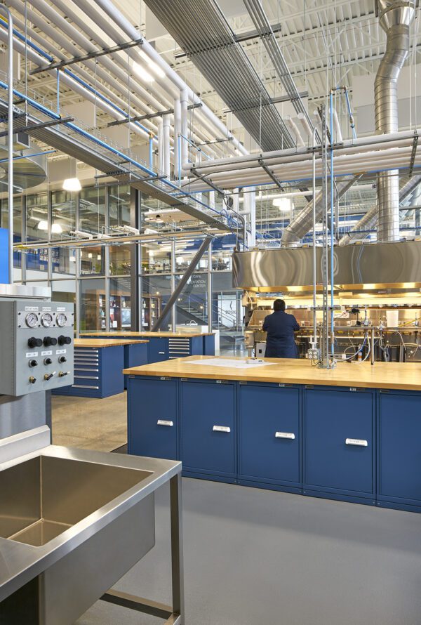
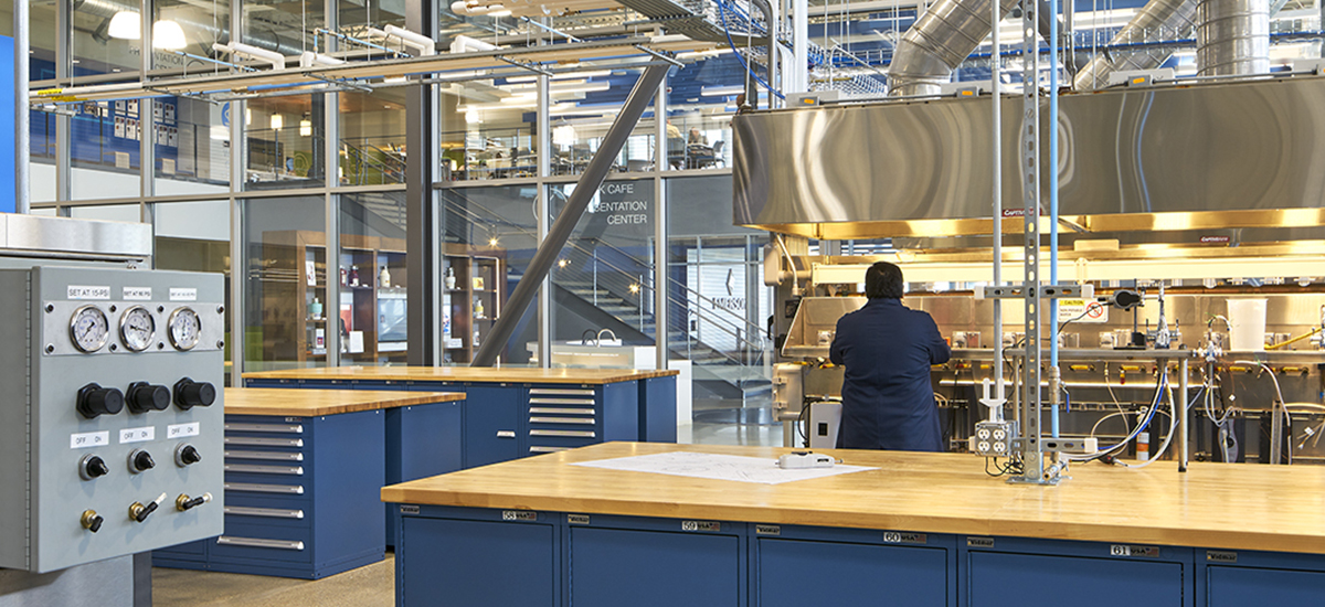
Fig 1: For some process water systems, facility managers can reclaim the energy from the process and in some cases, even reclaim the effluent itself. Courtesy: McClure Engineering
Leadership in Energy and Environmental Design (LEED) certification
LEED is a great system to encourage the design/construction of more sustainable buildings. As more buildings move toward LEED certification, this energy/water reclaim system can help achieve points within the LEED rating system. The energy savings and design can qualify for “energy savings” or “innovation” LEED points.
Energy efficiency for process water systems
Process water systems for research no longer need to be a large energy/water drain for a facility. Innovative solutions can save money and help the environment at the same time. In addition, the payback on these types of systems is often reasonable. Thus, the decision to install is often economically feasible and sound. As many companies start to set carbon-neutral goals, energy/water recovery systems will continue to become more relevant and viable for designers and facility managers.

Erik Eaves, P.E.
Published April 2, 2022 in Control Engineering
Erik Eaves, PE, is a principal at McClure Engineering. Edited by Chris Vavra, web content manager, Control Engineering, CFE Media and Technology, cvavra@cfemedia.com.
