Squeezing Maximum Efficiency Out of Your Condensing Boilers
Principal Randy Hassler discusses condensing boilers and putting it all together for maximum annual efficiency.
If you don’t read past the first paragraph of this article, the one takeaway I want you to have is that a hot water boiler does not determine the system’s delta-T (ΔT). Instead, the boiler heats the return water up to the operating set point. The system ΔT is the weighted average of the loads along the type of control valves (2-way vs. 3-way), and how the boilers are piped and pumped.
Let’s walk through a quick history review of hot water boilers and system piping. With early systems, simplicity was the key factor using constant speed pump(s) and constant volume systems with 3-way control valves. Early boilers were noncondensing and had simple on-off or low-high-low fire controls, where the constant flow provided a large flywheel for the boiler operating controls. These early systems consumed significant pumping energy if the heating system operated year-round. As energy became more important in system design, engineers realized that most of the pumping energy was in the distribution system because it had higher head. Engineers developed a constant flow primary and variable flow secondary pumping arrangement with a hydraulic decoupled bypass, allowing the two loops to operate independently. The variable flow secondary with 2-way control valves allowed the flow to be varied with the load and the energy to be reduced from varying the secondary flow. The constant flow primary pumping didn’t fundamentally change how the boiler operated and worked universally with either a high- or low-mass boiler. The primary pump head is typically low, so the constant volume pumping energy isn’t a significant energy penalty. Existing constant volume systems could also be easily retrofitted to primary-secondary with the addition of primary pumps and a bypass; the existing system pump(s) would serve as the secondary pump(s). Prior to variable-speed drives (VSDs) being widely available and cost-effective, a pump without a VSD with a system of 2-way valves simply “rode” the pump curve as flow was reduced. This reduced power by approximately the square of the flow. With a VSD, the pump power reduction is approximately the cube of the flow. With noncondensing boilers, the boiler efficiency is correlated to the boiler leaving water temperature and stack temperature independent of the return water temperature. Therefore, how the boiler is piped, and the type of control valves used on the loads has a negligible effect on boiler efficiency.
Table 1: A comparison of boiler thermal efficiencies with different piping arrangements.
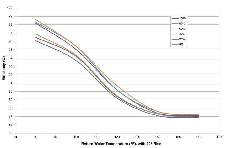
When using a condensing water boiler, the fuel to water thermal efficiency is mostly dependent on the return water temperature along with the percent firing rate, as illustrated in Figure 1. The efficiency gain at lower return water temperature is the result of the counterflow heat exchange with the flue gas and condensing water vapor in the flue gases, recovering its latent heat of vaporization, which would otherwise have been wasted up the flue. The lower the return water temperature, the greater the amount of condensing and, therefore, greater efficiency of the boiler. Modern metallurgy of condensing boilers has been designed to withstand the corrosive condensate to allow these efficiency gains. The piping and pumping of the boiler system will have an impact on the return water temperature and efficiency realized through the full range of operation, not just the “design” case.
Figure 1: Condensing boiler thermal efficiency.
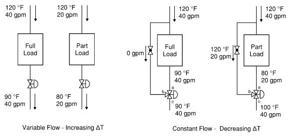
Figure 2 illustrates a typical air heating coil controlled by space temperature. This is similar to other types of loads where the control valve is controlling the secondary process. At full load, both are the same system flow and system ΔT. However, at part load, the ΔT is very different at the system level. With a 2-way control valve, the flow will be reduced, and the ΔT will remain constant or increase at part load depending on how the process variables change. With a 3-way control valve, the system flow will be constant, and the system ΔT will be less than the design case. Closely examine the part-load flow of both control valve types and the leaving water temperature at the coil. Notice it is the same in both cases. The coil doesn’t know what type of control valve the designer selected.
Figure 2. A comparison of 2-way and 3-way control valves on system flow and temperature drop.
With each load in a system, the flow and ΔT are determined by the type of equipment and the availability of selection parameters to the designer. A large central station air-handling unit, for example, has coil choices with different rows, fins per inch, and circuiting such that a system designer can pick a reasonable target ΔT that is achievable with the adjustment of the various parameters with the tradeoff of performance and cost. A packaged fan coil unit or other terminal equipment may only have two coil choices available, standard capacity and high capacity, which requires adjusting the flow rate until satisfactory heat output capacity is reached and the water side ΔT is determined for the designer. Your system will have a mix of loads with a design capacity and a design flow rate for each. To determine what the design return water temperature is, one must calculate the weighted average of all the loads. The part-load return water temperature will also be the weighted average of the part-load performance of all the loads and how the system is piped and pumped.
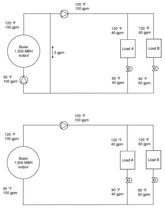
Now, let’s look at how both variable primary and primary secondary effect the return water temperature to the boiler, and, thus, the efficiency in a condensing boiler. Comparing Figure 3A: primary-secondary and Figure 3B: variable primary at full load, the return water temperature to the boiler is the same.
Figure 3A. Primary – secondary boiler system at full load.
Figure 3B. A variable primary boiler system at full load.
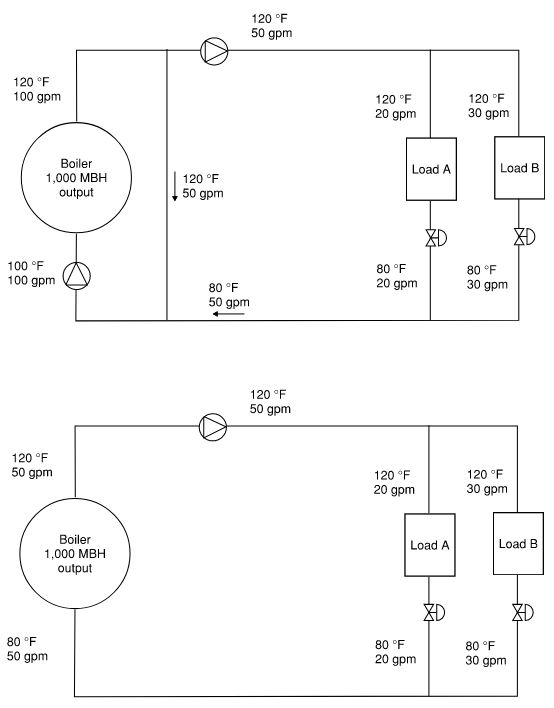
Comparing Figure 4A: primary-secondary and Figure 4B: variable primary at part load, the return water temperature to the boiler is lower in the variable primary case. With a primary-secondary piping arrangement, the excess primary flow at a higher supply water temperature mixes with the return water temperature for a blended return water temperature to the boiler that is higher than the system return temperature. Referring to Figure 1, in the efficiency curves for both Figure 4 cases, there is a 2.7% increase in boiler thermal efficiency for the variable primary piping arrangement. Only high-mass boilers can be piped variable primary due to the large water volume and flywheel effect when the load changes and the boiler controls respond. A low-mass boiler would overshoot or undershoot with quick load fluctuation.
Figure 4A. A primary- secondary boiler system at part load.
Figure 4B. A variable primary boiler system at part load.
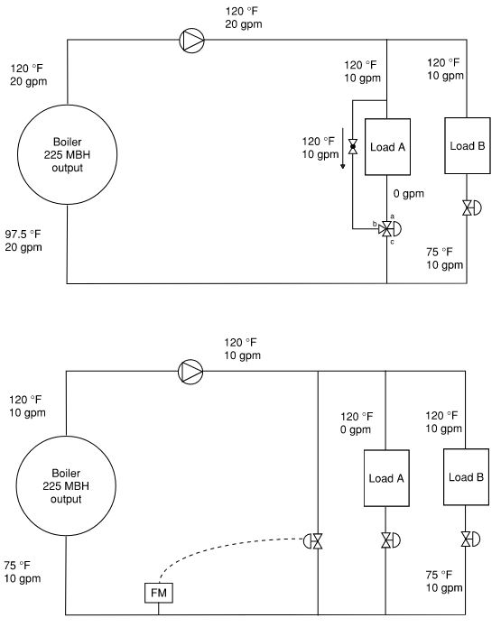
With a variable primary arrangement, the boiler minimum flow rate needs to be considered. There are two common methods if the sum of the minimum loads is less than the boiler minimum flow rate (based on burner turn down and boiler efficiency at part-load return water temperature). For this example, assume the minimum flow rate is 10 gpm. Figure 5A shows the use of a 3-way control valve on a load to control the system minimum flow. During system water balancing, the minimum pump speed can be established with all the control valves closed such that the system flows 10 gpm through the bypass of the 3-way valve. Now, if Load B has a part-load demand of 10 gpm, the total system flow is 20 gpm. Note that with the variable volume example, with a 3-way control valve, the flow through the bypass is proportional to the pump speed. As the pump speed increases to satisfy other loads, the flow through the 3-way valve bypass will increase up to its design value. Using the early example, it would be 40 gpm, a significant amount of unwanted supply water bypass at part load. Figure 5B shows the use of a 2-way control valve bypass to control the system’s minimum flow. A flow meter or differential pressure sensor can be used to modulate the bypass valve.
Comparing Figures 5A and 5B, the return water temperature is lower in 5B and will have higher efficiency. Referring to Figure 1, efficiency curves for both Figure 5 cases demonstrate a 2.7% increase in boiler thermal efficiency for the bypass control method. (Note that Figure 1 is at a 20°F rise. To determine the actual efficiency, one would have to have similar charts at each specific temperature rise.)
Figure 5A. A variable primary boiler system at minimum flow with a 3-way valve.
Figure 5B. A variable primary boiler system at minimum flow with a bypass.
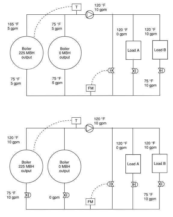
Lastly, with multiple boilers in a variable primary arrangement, we look at using a 2-position control valve interlocked to the boiler such that when the boiler is not operating, water flow does not circulate through the off boiler. Without the interlocked control valve, cold return water will flow through the offline boiler that will mix down the supply water temperature from the operating boiler. If the temperature sensor used by the boiler sequence controller is located in the header downstream of the boilers, then the online boiler must produce hotter water to meet the set point. If the boiler sequence controller used the discharge temperature of the online boiler as the system temperature, then the loads receive colder supply water than desired.
Figure 6A. A variable primary boiler without boiler isolation control valves. Figure 6B. A variable primary boiler with boiler isolation control valves.
While a couple of percentage points of boiler efficiency may not seem like much, the fuel cost operating savings goes straight to the business’s bottom line. Depending on the type of facility and the profit margins of the business, this same value of fuel savings may be the equivalent to a significant increased sale volume. Using the example of a $15,000 annual fuel-saving, if a business has a 10% profit margin, this will require an additional $150,000 of gross revenue to have the same $15,000 net revenue.
Thanks for reading to the end. I hope that there a few items that you learned, or it helped connect the dots of what you already knew.

Randy Hassler, P.E., LEED AP
Published June 7, 2021 in Engineered Systems Magazine
Randy Hassler, P.E., LEED AP is a mechanical engineer at McClure Engineering, a mechanical and electrical consulting engineering firm dedicated to the development of innovative solutions to unique engineering problems.

