School BAS: Out of Control!
Principal Check Dale-Derks discusses the importance of looking at how we are controlling our K-12 school HVAC systems for the spatial environment and comfort of the next generation.

Have you ever tried to drive a car without a speedometer? What about using the emergency brake instead of the brake pedal? If so, then you have experienced operation without proper or adequate control. The necessary controls are all present, but not using them effectively, or at all, can make a big difference in a successful driving experience. The same basic concept can be applied to HVAC systems in K-12 school buildings. Having the right controls means nothing unless they are being used properly.
As engineers, it is important to look at how we are controlling our K-12 school HVAC systems for the spatial environment and comfort of the next generation. In many cases, we have utilized the latest, web-based, direct digital control system with BACnet protocol and all the components necessary to do the job, but are we in control? Are we missing pieces or simply miscommunicating the intended operation? Do we even know how well the controls are operating? I recently worked with a school district on their K-12 campus and found multiple missing pieces or misapplied devices that caused problems in HVAC and added energy costs. In this article, I discuss the various issues we found at the school and some solutions we used to resolve them.
Hardware or installation issues
One of the first elements we tackled at the school was a missing feedback loop. In this case, the control manufacturer had a default program that, when the software called for a pump to start, it looked for the feedback status. If there was no status, then the program retried the start after a wait period. It repeated this effort three times and if there was still no status, it commanded the whole unit to switch off. The software then generated an internal alarm, but the operator was not alerted. As a solution, I had to instruct the control contractor to change the internal alarm to external. An alarm can’t be of value if it fails to alert someone. A simple investigation found that the current sensor needed the power wire wrapped instead of just the once-through to register the signal. The proper components were all present, just not installed and set up to operate as desired.
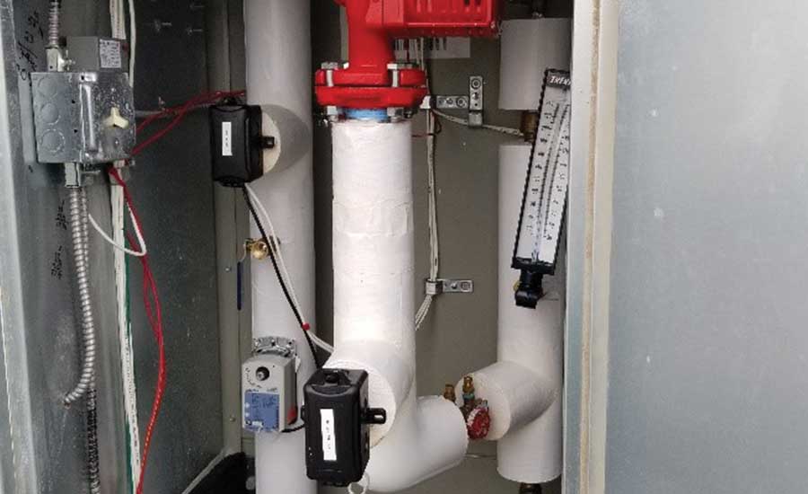
Figure 1: Preheat coil circulating pump mounted in the piping pocket of a rooftop unit.
Some other hardware or installation issues we found in the school included energy recovery wheels spinning backwards, overloads installed in the starter less than the motor nameplate amperes of the motor, an exhaust fan two-position damper not wired to open when the fan started and a hot water actuator that closed the drive valve but did not open it. In the case of the hot water actuator, maintenance had ‘fixed’ the issue by manually opening the valve daily to heat the space. Some comments from a contractor included: “EF15 was catawampus and needs new motor and bracket” and “Pump HWP1 started ramping up ‘haywire’, then drive went blank.”
The above observations were discovered by the team of engineers, maintenance staff, and multiple subcontractors, all working together, and corrected to achieve a better performing building.
Misapplied software issues
Misapplied software issues were also creating issues in the buildings. A chain reaction of problems arose when the energy recovery wheel status was not being received. Without the status, the preheat valve was held closed, and then the low limit switch tripped to shut down the unit. Other observations found the outdoor air temperature manually fixed in some HVAC units instead of being transferred from the central controller, which didn’t allow the units to operate properly. We found a bypass valve at 0% closed, so the unit is operating in reverse of the way it should. Having trends set up as 600 seconds instead of 30 seconds made it impossible to verify proper sequence of operation, until this was corrected. Having proportional-integral-derivative (PID) loops wound up at start-up and/or not using an optimized start with a warm-up cycle also created issues. Startup of units should be set up with a balanced approach around a building, as opposed to a numerical order approach.
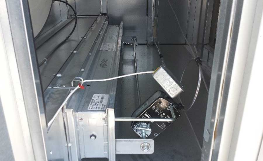
Figure 2: Energy recovery wheel bypass damper with actuator mounted on near side and linkage on the far side. This has the jackshaft bent at the onset and increases susceptibility to failure.
Control system communication confusion and issues
Control system communication confusion and issues were also preventing proper operation in the buildings. Remote access was either not set up, or there were no specific operator login credentials established until well after the substantial completion of the system. The district IT department required a specific virtual private network, which can limit access or takes weeks to establish. There were also eight maintenance members using remote access through one central computer to access 12 of 22 facilities.
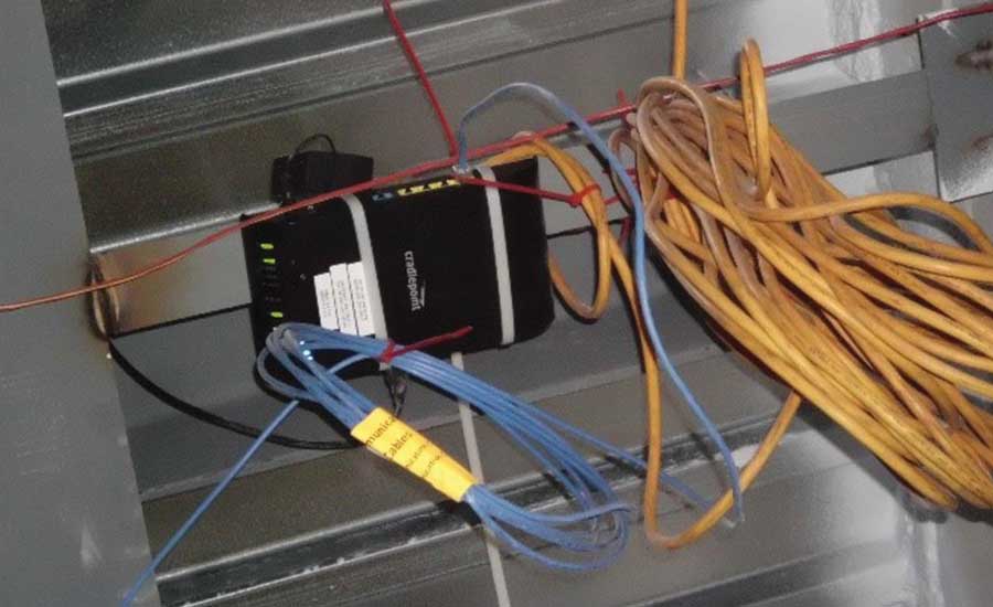
Figure 3: A temporary wireless access point for communication off-site to the temperature controls contractor’s office. Use prior to the school district’s network being activated.
Communication issues between engineers and contractors
Miscommunication between engineers and contractors can lead to problems as well. In this job, we ran into communication issues with building plans. The plans had labeled fan coils “FCU-A” at every door because they were all the same size and model, but the controls for the fan coils were labeled FCU-1 thru 14 without documentation. This made it difficult to trouble shoot and monitor the fan coils. Sometimes the control contractor’s intent is vague and the installed systems that set out to achieve their intent hit a different mark. Some of the “fixes” we ran into by the control contractor included the increase of the VAV box max heating cfm to max cooling cfm. This added significant load and impacted the performance of the preheat coil. As a result, there was a massive amount of wasted energy and the heating system struggled to keep up. Another “fix” we encountered was to prevent freezing in the system. The preheat coil control valve was wide open during hours when the building was unoccupied, with the unit supply fan off and all dampers closed. This caused heating water pumps to run at 100% speed all night long. Those same pumps normally operated at 35% speed during the occupied period of the building. Trends, as shown in Figure 4, help locate these operating issues.
The Flow Diagrams we used for the job are a schematic representation of the system. They show general locations of control points, some of which needed more specific instruction or additional detail that were shown on the plans.
Points lists (like the one shown in Image 6) link the flow diagrams and specifications, list sensor types and note new versus reused or modified points. They also provide a link between flow diagrams and sequences of operation, and call out action items, alarms, trending and graphics requirements. Points lists can also indicate hardwired versus software-controlled points. For example, fans and pumps should operate in “Hand” as wired by an electrical contractor and should operate in “Auto” as wired by a BAS or controls contractor.
Sequences of Operation are word problems that are interpreted by the temperature controls contractor and essentially describe the brains of the operation. This is where miscommunication happens most often, due to a controls contractor’s approach of using canned programs or standard blocks instead of a clear, customized block that meets the proper and intended sequence. PID loops need graphs to clarify the operation, such as the one shown in Figure 7.
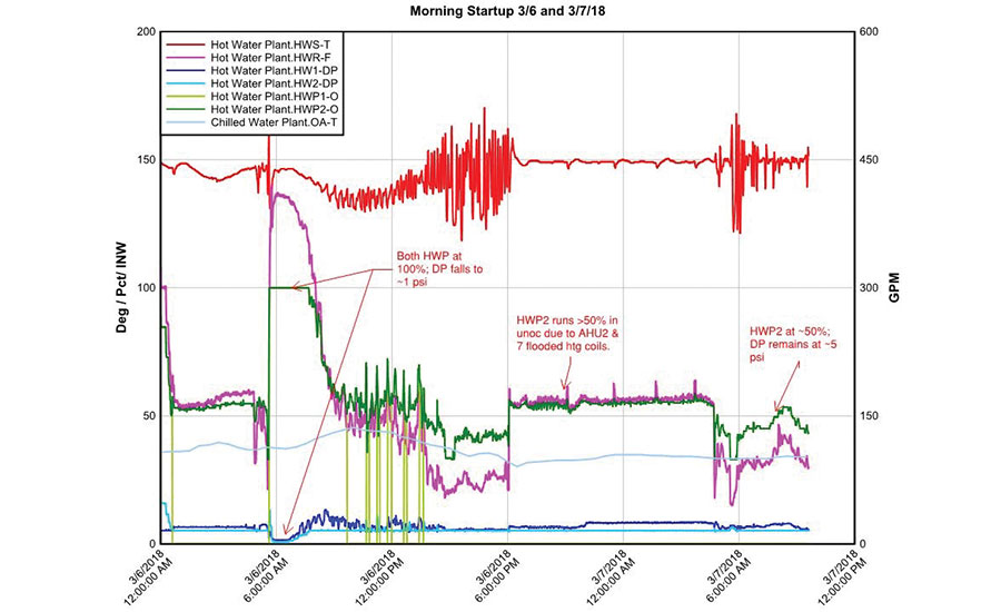
Figure 4: Multiple trends, with samples every 30 seconds, plotted together allow data to be visually analyzed quickly.
Interlock/ladder Diagrams provide safety (hardwire) interrupt of equipment. However, this is often a scope resolution as to whether these are wired by the project electrician or the temperature controls electrician. They do ensure safeties are wired as intended and that they interact properly to shut down equipment. For example, low limit switches should stop fans and interrupt control signals so that normally open control valves open to their safe position and normally closed dampers close to their safe position.
Engineers’ role in assessing and resolving the issues
It is an engineers’ responsibility to understand what the client needs. Most often, it is about finding a balance among reliability/redundancy, energy conservation, initial cost, simplicity/maintainability and quick installation. There are questions we must ask ourselves during the planning and assessment of a building that will help us find those balances.
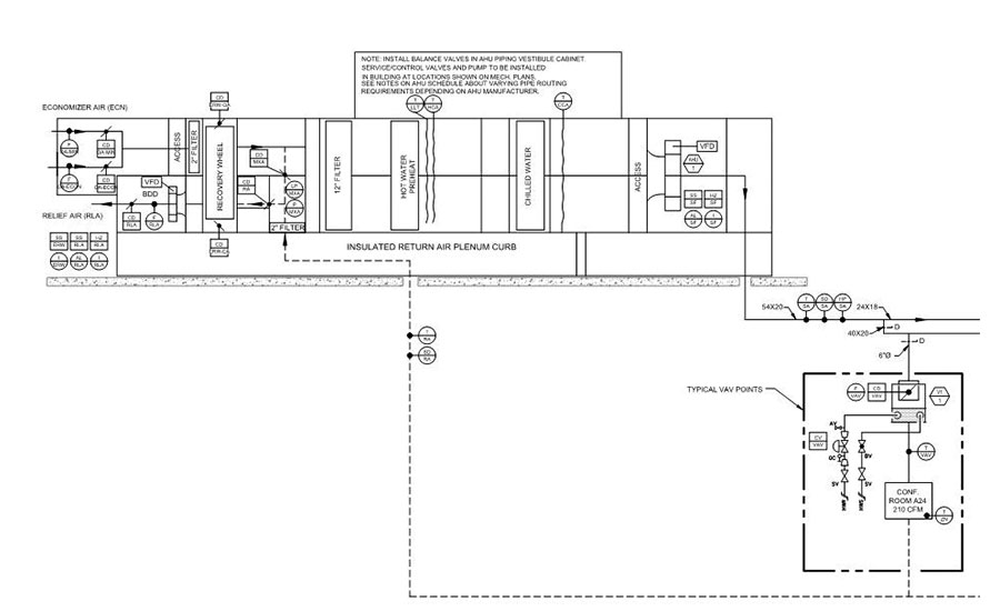
Figure 5: AHU flow diagram with control points.
For chillers and boilers, are we controlling temperature or flow? Equipment technology will determine chilled and condenser water flexibilities, but we must also ensure the controller card speaks the correct language. For pumps, are we controlling lead-lag or simultaneous operation? Engineers should consider something other than a 50/50 time split in lead-lag so as not to wear pumps equally. Differential pressure sensor location(s) for pumps and fan systems should also be considered carefully. My recommended approach is to have a differential pressure sensor located in the plant with the pumps and the local controller but allow the pressure to be reset by remote sensors at hydraulically remote AHUs with values communicated across the network. For cooling towers, we might need to control fan speeds on multiple modules. Attempting to control cooling tower fan speeds on an approach to outdoor air wet bulb temperature will ensure the fans can operate at reduced speeds and not try to meet a condenser water temperature that the cooling towers cannot deliver. Applying variable speed pumping to condenser water pumps requires knowing if the open circuit minimum pump differential will carry enough lift to flow over the tower and knowing the minimum flow of the tower in order to prevent icing where free cooling modes are implemented. For VAV boxes with reheat, the optional discharge temp sensor is a necessity where the maintenance staff are stretched over multiple buildings. The ability to remotely observe the feedback of the discharge temperature allows for remote testing of the box. In any and all cases, engineers must know their equipment’s limitations.
Necessity of scheduling
Complexity in jobs requires planning ahead, usually in the form of a start-up schedule. A start-up schedule requires diligent attention and may follow the example sequence below:
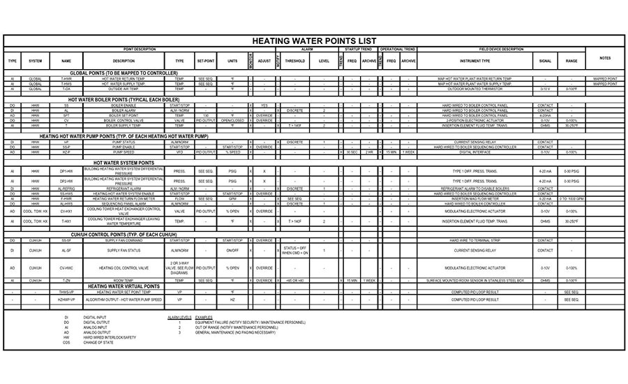
Figure 6: Heating Water Point List
AHU/RTUs shall stagger occupancy over a 10-minute period (adjustable) to reduce impact to fan volume control and central plant heating and chilled water control. For each of the defined schedules, the weekly occupancy shall be as follows:
- Normal Occupancy Schedule shall be from 6:00 AM to 4:00 PM (user adjustable with temporary timed override). Cooling set point shall be 75°F and heating set point shall be 70°F. Ventilation shall be for normal occupancy. Exhaust fans shall be on.
- Custodial Occupancy Schedule shall be from 4:00 PM to 11:00 PM (user adjustable). Cooling set point shall be 78°F and heating set point shall be 68°F. Ventilation shall be set to 50% of the design minimum outside air or the total of the exhaust fan airflows serving the same areas as each AHU whichever is greater. Exhaust fans shall be on.
- Unoccupied Schedule shall be from 11:00 PM to 6:00 AM Monday through Friday, Weekends, and Holidays (user adjustable). Cooling set point shall be 80°F and heating set point shall be 65°F. Ventilation shall be disabled. Exhaust fans shall be off.
- User Adjustable Override Schedule: A user adjustable override schedule shall be included to allow the user to schedule events either during and/or after normal operating hours. The event schedule shall override the system during the times entered and shall automatically revert to the normal occupancy schedule after the programmed event expires. This schedule shall have the ability to program events 1-year in advance and shall be capable of programming multiple events per day throughout the year.
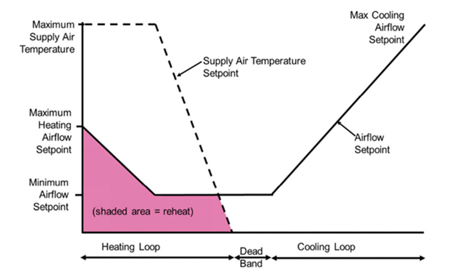
Figure 7: A graphic of the intended control sequence.
There is no need, and no benefit, to ventilating a building that is unoccupied or is only partially occupied. This is more of a challenge for school districts as they increase meetings, activities or the outside use of parts of the building. Energy can be managed by aggressively monitoring and controlling the ventilation rates and schedules of the building. As I touched on earlier, proper use of the controls is just as important as the controls themselves.

Chuck Dale-Derks, P.E.
Published April 9, 2018 in Engineered Systems
Chuck Dale-Derks, P.E., is a principal at McClure Engineering, a mechanical and electrical consulting engineering firm dedicated to the development of innovative solutions to unique engineering problems.