Consider All Mechanical Engineering Options Before Investing in a Campus Expansion
Principal Phil Wentz uses past McClure Engineering projects to illustrate everything you need to know before embarking on a Campus Expansion.

Campus expansion has always challenged the associated growth of a centralized chilled water and heating water plant. Central plants, by design, are centrally located and often become landlocked by the growth of the campus served. At the same time, the central plant is often the most desired real estate in terms of campus function as well as aesthetic beauty. As the campus expands, the distribution piping needs to be extended. The associated losses, both thermal and hydraulic, increase as the piping insulation deteriorates and the piping runs see higher flow rates.
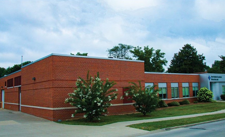
Figure 1: The central plant at Southern Illinois Healthcare Carbondale’s hospital incorporates facility offices and a data center.
Depending on campus growth, both in terms of physical boundaries and functions of adjacent structures, there are several strategies to address growth of campus cooling and heating loads. Engineers typically see three options: (a) renovation of an existing central plant, (b) the creation of a new central plant, or (c) distributed smaller plants incorporated into campus buildings.
A comprehensive campus building control system is paramount in maintaining visibility and automation of the equipment operation. A level of performance analytics, either manually or automated, can identify equipment performance issues before they become a crisis. This allows facilities personnel to maintain equipment rather than continually chase the next problem.
Some central plants are just outdated and in need of a renovation. They are in an appropriate location, structurally sound with suitable tunnels, or piping radiating to the campus loads. The central plant equipment may be inefficient or the design suffers from the limitations when it was first configured more than 30 years ago. Typical modifications designed to improve efficiency include steam to hot water conversions (reduction of distribution losses), heat recovery chillers or boilers sized for summer loads, chillers sized for winter loads, and improved distribution piping and tunnels as necessary.
Campus expansion can leave the existing plant either in an inefficient location to support the new growth or in the perfect place to add the next building. Either possibility is an opportunity to build a new central plant from scratch. One of our hospital clients asked us to take such an opportunity to create a new chilled water plant, which included a hardened structure to thwart natural disasters and a campus-wide data center and backup power with room to grow to back up the entire hospital.
The campus growth resulted in the plant not being centrally located but placed across the street in a mixed commercial and residential location. The plant utilizes attractive barrier walls to mitigate cooling tower and generator noise from the adjacent properties. Acoustical measurements taken before and after verified the noise levels were not increased by the new plant. Additionally, the hospital maintenance staff was relocated in the new plant to free up space on campus. The old plant was converted to mainly a heating plant but also includes a heat recovery chiller for summer heating needs and a redundant conventional chiller.
Many of our larger campus projects have morphed into distributed chilled water and/or heating water plants. As the campus grows, distributed plants are sized to serve the campus master plan and located strategically to facilitate efficient distribution as well as redundancy and maintenance. Ideally, three to six plants provide manageable capacities and redundancy, but often there are more as the campus growth accelerates past the master plan.
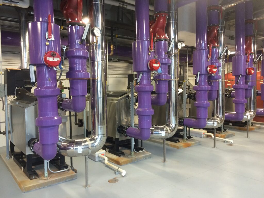
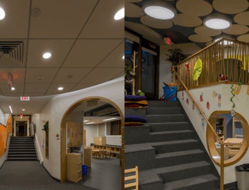
Figure 2: The interior of the distributed and chilled water plant at Missouri University of Science & Technology, Rolla.
A large, new building can incorporate a plant that can serve most of the new building load as well as absorb the cost of the plant. The key is that the equipment must be sized for its most efficient operation and not its peak operation. This may mean a plant has a pair of smaller boilers or chillers able to turn down to meet the minimum load. A larger set of equipment can be combined to cover the peak load either in the same plant or a plant in a different location. The old plant can be decommissioned completely or reduced in capacity to complement the campus distributed plants rather than serve the whole campus. A level of redundancy should be incorporated into a distributed “central” plant concept to address equipment failure, plant renovation, and utility work that may interrupt piping to certain areas.
A piping distribution system links the plants together for optimum redundancy and efficiency. We have used one-, two-, and four-pipe campus wide distribution system topologies. The four-pipe system, chilled and heating, water, supply and return provide both the greatest flexibility and cost. Most of the cost in underground piping is in the trench or tunnel rather than the pipe. The developments of high-density polyethylene (HDPE) and fiberglass piping have led most of our utility piping to be directly buried with jacketed insulation. Tunnels are still wise when they are in good condition or allow maintenance access in an urban environment.
The beauty of a central plant was one could “watch” a plant by walking through the building and observing the sounds and gauges on the equipment. As the plants grew and control rooms were developed, fewer walks were taken. The campus-wide control system with an intuitive dashboard reporting equipment status allows operators to see all the plants at once. Automation sequences that provide feedback on the dashboard as to when equipment will be started or stopped takes the guesswork out of the operator’s mind if they need to override something. A distributed plant scheme should have the same control system vendor for control and operation of the valving and pumping effecting the distribution piping. Buildings should be configured as stand-alone entities with different control systems if necessary. Often, different building ages result in different control systems platforms, even if they are from the same manufacturer.
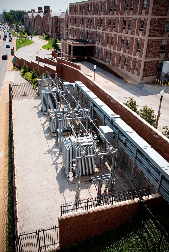
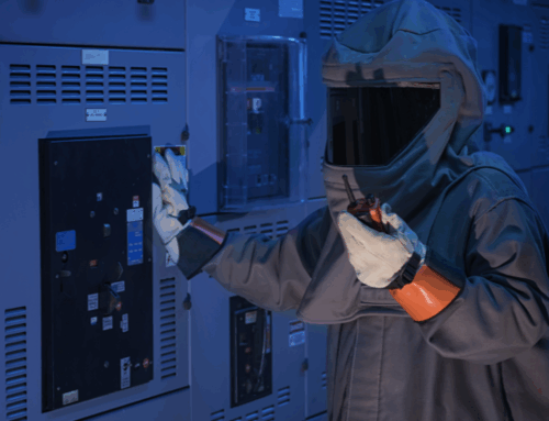
Figure 3: A look at Washington University, St. Louis’ centralized campus electrical distribution equipment.
Fifty years ago, central plants generating high-pressure steam for heating could also economically produce electrical power. Today, the cost of cleanly burning coal and the scale required to generate electricity with gas economically has eliminated most small production of electric power. The central electrical substation is another opportunity to consider what makes sense and how to grow efficiently while taking benefit of the overall campus demand. It’s good practice to typically locate chilled and hot water plants on different medium-voltage loop feeds to provide redundancy if a cable or switch needs to be replaced.
As a campus expands, one must pay attention to the master plan and how the campus will grow in five, 10, 20, and 50 years. It is important to plan ahead with plant locations, power distribution, duct banks, and utility corridors. Campuses should work with the local utilities to keep the utilities in the street updated and maintained. The overall energy efficiencies of central plant design in whatever form it takes will typically prevail over a stand-alone MEP system assuming the distribution piping length is reasonable.

Phil Wentz, P.E.
Published August 13, 2018 in Engineered Systems
Phil Wentz, P.E., is a principal at McClure Engineering, a mechanical and electrical consulting engineering firm dedicated to the development of innovative solutions to unique engineering problems.