Tech Topic: An Effective Bypass Flow Control Strategy for A Decoupled Chilled Water Plant
Ajay Bhargava discusses the inherent flaw of delaying the start of another chiller until the bypass flow reading is close to zero gpm.

Both as a tool for starting an offline chiller and as a reliable indicator for stopping an online chiller, it makes sense to use chilled water (CHW) flow reading through a decoupled bypass leg.
A decoupled CHW plant is one where flow and head produced by pumps in the primary loop are unaffected by flow and head produced by pumps in the secondary loop. The section of CHW piping, common to both the primary and the secondary loops, is called the bypass leg. If the bypass leg sees negligible pressure drop, it is considered a decoupled bypass leg.
If the bypass leg sees warm, return chilled water flow, it is classified as bad bypass flow (positive sign convention). However, if it sees cold supply chilled water flow, it is classified as good bypass flow (negative sign convention).
Over the years, quite a few plant operators and control engineers have taken an overly simplistic approach of delaying the start of another chiller until the bypass flow reading is close to zero gpm. However, this approach has an inherent flaw. It has made many plant operators either disappointed due to unacceptably high CHW supply temperatures or incorrectly conclude that a de-coupled chilled water plant does not work.
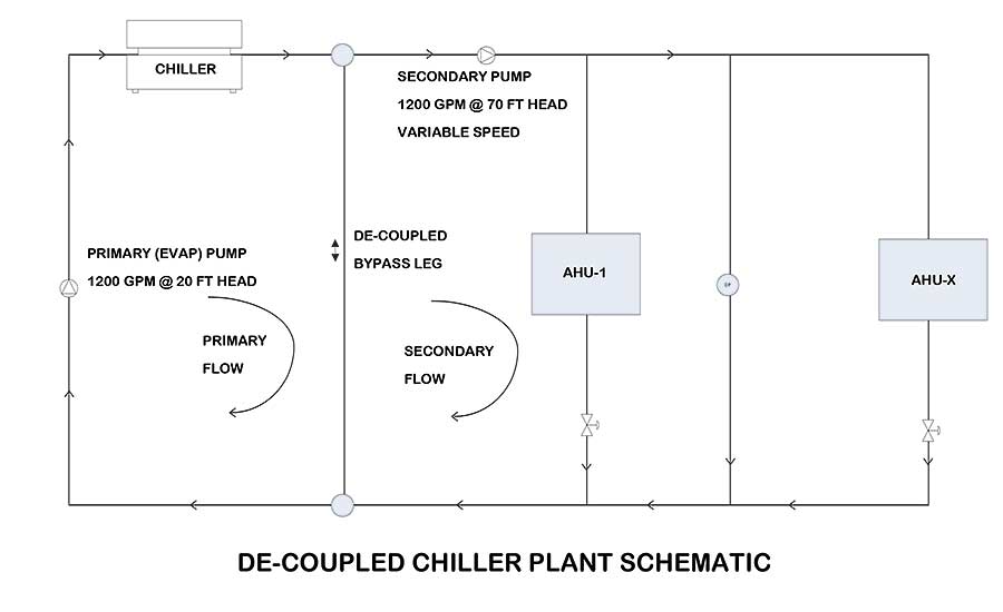
Figure 1: De-Coupled Chiller Plant Schematic
The flaw is in the assumption that the secondary side chilled water temperature difference (CHWDT) can never get higher than the primary side CHWDT under off-design load conditions. In fact, for partly loaded CHW cooling coils that see turbulent air and water flows, have two-way control valves for CHW flow control and are sized correctly, it can be theoretically shown that secondary side CHWDT will be higher than primary side CHWDT. This is a direct contradiction of the assumption.
Lowering the chiller plant CHW setpoint to below design, running excessive number of chillers and installing a check valve in the bypass leg are some of the “fixes” plant operators have implemented over the years to address this flaw. However, these fixes result in a significant energy penalty and are not desirable. Installing a check valve or control valve in the bypass leg defeats the concept of a decoupled chilled water plant and is ill-advised.
Show me the numbers
In lieu of a fixed bypass flow setpoint of zero gpm and energy-inefficient measures taken to mask the flaw, a better approach is to use a bypass flow setpoint (BYPGPMSP) reset based on a mathematical formulation as listed below.
BYPGPMSP = Minimum (0, PCHWGPM * ((PCHWDT/ SCHWDT) – 1))
Where PCHWGPM = Primary side CHW flow (gpm),
PCHWDT = Primary side CHWDT (°F),
SCHWDT = Secondary side CHWDT (°F)
Calculation for a bypass flow setpoint can be enhanced to handle de-rating of chiller plant capacity due to age, higher than design condenser water supply temperature and other field performance issues.
BYPGPMSP = Minimum (0, PCHWGPM * ((PCHWDT * CAPCORR/ SCHWDT) – 1))
where CAPCORR is a custom capacity correction factor for the chiller plant
To illustrate how the bypass flow set-point calculation works, four comparative operating scenarios are summarized below.
Scenario #1: PCHWGPM = 1,200 gpm, PCHWDT = 10° F, SCHWDT = 8° F, CAPCORR = 93% = > BYPGPMSP = 0 GPM
Scenario #2: PCHWGPM = 1,200 gpm, PCHWDT = 10° F, SCHWDT = 10° F, CAP CORR = 93% = > BYPGPMSP = -84 gpm
Scenario #3: PCHWGPM = 1,200 gpm, PCHWDT = 10° F, SCHWDT = 12° F, CAPCORR = 93% = > BYPGPMSP = -270 gpm
Scenario #4: PCHWGPM = 1,200 gpm, PCHWDT = 10° F, SCHWDT = 14° F, CAPCORR = 93% = > BYPGPMSP = -403 gpm
The only variable that has changed in scenarios 1 through 4 is the secondary side CHWDT. As the secondary side CHWDT increased from 8° F to 14° F, the calculated bypass gpm setpoint decreased from 0 gpm to -403 gpm, which is significant for a plant with primary flow of 1,200 gpm. If the bypass flow is not controlled at or below the setpoint for a significant time period, it will result in unacceptably high CHW supply temperatures.
The difference between bypass flow setpoint and bypass flow can provide an estimate of the leftover capacity at the plant as follows:
AVAILCAP = MAXIMUM (0, (BYPGPMSP – BYPGPM) * SCHWDT/ 24)
Where AVAILCAP is the leftover available capacity (TONS) at the chiller plant,
BYPGPMSP is the calculated bypass flow set-point (GPM),
BYPGPM is the flow through the bypass leg as per sign convention (gpm),
SCHWDT is the secondary side CHW delta-T (°F)
If the leftover capacity is below an acceptable threshold for a chiller to be started, it can be proactively used to start another chiller without losing control of CHW supply temperature. The acceptable threshold for starting a chiller (STARTLIMIT) can be a fixed value or can be reset based on the outdoor air wet bulb (OAWB) temperature. An alternative approach, based on CHW supply temperature exceeding, say 48° F, is less preferable since it is a reactive approach and can result in the secondary CHW supply temperature to spiral out of control.
STARTLIMIT = STARTLOW + (STARTHIGH – STARTLOW)/ (OAWBHIGH OAWBLOW) * MAX (0, (OAWB – OAWBLOW))
Where STARTLOW = 50 tons (user adjustable),
STOPHIGH = 200 tons (user adjustable),
OAWB = Outdoor air wet bulb temperature (°F),
OAWBLOW = Low-side OAWB = 40° F (user adjustable),
OAWBHIGH = High-side OAWB = 80° F (user adjustable)
If the leftover capacity is above an acceptable threshold for a chiller to be stopped, it can be reliably used to stop a chiller. The acceptable thresh-old for stopping a chiller (STOPLIMIT) is typically the capacity of the chiller selected as next chiller to be stopped plus a dead band that is reset based on OAWB. Extended operation of poorly loaded chillers is thereby avoided.
STOPLIMIT = STOPCHILLERCAP + DBSTOPLOW + (DBSTOPHIGH – DBSTOPLOW)/ (OAWBHIGH – OAWBLOW) * MAX (0, (OAWB – OAW-BLOW))
Where STOPCHILLERCAP = Capacity of chiller selected as next chiller to be stopped (tons)
DBSTOPLOW = Low-side dead band for stopping chiller = 150 tons (user adjustable),
DBSTOPHIGH = high-side dead band for stopping chiller = 350 tons (user adjustable),
OAWB = Outdoor air wet bulb temperature (°F),
OAWBLOW = Low-side OAWB = 40° F (user adjustable),
OAWB_HIGH = High-side OAWB = 80° F (user adjustable)
Reliable decisions to start/stop chillers are predicated on the accuracy of the bypass flow reading. The bypass pipe leg should have a straight pipe length of at least 12 pipe diameters for ensuring accurate readings with a non-invasive flowmeter.
In conclusion, flow reading in the bypass leg of a decoupled chiller plant is of great significance, and it can be applied to reliable chiller start/stop controls.

Ajay Bhargava, P.E., CEM
Published December 30, 2019 in PM Engineer
Ajay Bhargava, P.E., CEM, is a mechanical engineer at McClure Engineering, a mechanical and electrical consulting engineering firm dedicated to the development of innovative solutions to unique engineering problems.