Deciphering the Codes for Fire Protection Standpipes
There are considerations for the standpipes’ locations, sizes, pressure and flow that all must be addressed before a commercial building can be occupied.
")
Learning Objectives
- Identify the codes and standards associated with fire protection standpipes.
- Achieve a better understanding of when to specify, what type and the location of the standpipes required.
- Recognize the size, pressure and flow requirements of a standpipe.
Standpipe insights
- For areas where required by code, fire protection standpipes and their associated hose valves are critical pieces of fire protection equipment in commercial buildings.
- It is important to understand these codes along with how, when and where they apply.
Fire protection standpipes are a critical part of the overall safety of a building when they are required by code and authorities having jurisdiction (AHJ). Standpipes with hose connections when present throughout a building allow firefighters to connect to a water source more readily. These pipes are crucial in helping to get water to fight fires in hard-to-reach places and ultimately minimize the hose length and weight of equipment for the firefighter.
With such a critical piece of firefighting equipment in a commercial building, especially high-rises, there is to be a considerable amount of complexity and detail associated with them. There are considerations for the pipes’ locations, sizes, pressure and flow that all must be addressed before a building can be safely occupied. Building codes and standards guide us in these requirements.
There are three formal documents that must be considered when planning for standpipes. These documents include the International Building Code (IBC) (2021), NFPA 14: Standard for the Installation of Standpipe and Hose Systems (2019) and NFPA 13: Standard for the Installation of Sprinkler Systems (2019).
When are standpipes required?
The IBC covers when standpipes are a required installation. Three frequent instances will be discussed within this article. The first indication that standpipes are required is related to the building’s height. According to IBC Section 905.3.1,
- Class III standpipe systems shall be installed throughout buildings where any of the following conditions exist:
- Four or more stories are above or below grade plane.
- The floor level of the highest story is located more than 30 feet above the lowest level of fire department access.
- The floor level of the lowest story is located more than 30 feet below the highest level of fire department vehicle access.
Another situation addressed by the IBC concerns nonsprinklered assembly occupancies. According to IBC Section 903.3.2 Group A, “Class I automatic wet standpipes shall be provided in nonsprinklered Group A buildings having an occupant load exceeding 1,000 persons.”
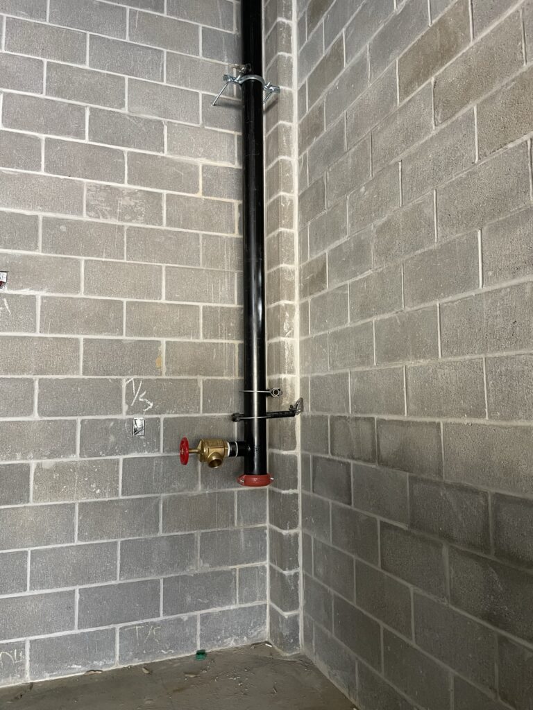
Figure 1: Simple standpipe with a hose valve connection.
- This comes with two specific exceptions:
- Open-air-seating spaces without enclosed spaces.
- Class I automatic dry and semi-automatic dry standpipes or manual wet standpipes are allowed in buildings that are not high-rise buildings.
The final instance being discussed is related to stages. IBC Section 905.3.4 states, “Stages greater than 1,000 square feet in area shall be equipped with a Class III wet standpipe system with 1½ inch and 2½ inch hose connections on each side of the stage.”
While IBC identifies the “Class” of standpipe required within the building, NFPA 14 defines the requirements of the “Class.” Per NFPA 14, a Class I system is one that “provides 2½ inch hose connections to supply water for use by fire departments.” A Class II system is one that “provides 1½ inch hose stations to supply water for use primarily by trained personnel or by the fire department during initial response.”
Finally, a Class III system is a combination of a Class I and Class II system. This indicates that it “provides 1½ inch hose stations to supply water for use by trained personnel and 2½ inch hose connections to supply a larger volume of water for use by fire departments.”
What type of standpipe is required?
NFPA 14 provides a definition for the different types of standpipe systems.
Section 3.3.17 definitions:
Automatic dry standpipe
A standpipe system permanently attached to water supply capable of always supplying the system demand, filled with air or nitrogen under pressure, the release of which opens a dry pipe valve to allow water to flow into the piping system and out of the opened hose valve.
Automatic wet standpipe
A standpipe system always containing water that is attached to a water supply capable of always supplying the system demand and requires no action other than opening a hose valve to provide water at hose connections.
Manual dry standpipe
A standpipe system with no permanently attached water supply that relies exclusively on the fire department connection to supply the system demand.
Manual wet standpipe
A standpipe system always containing water that relies exclusively on the fire department connection to supply the system demand.
Semi-automatic dry standpipe
A standpipe system permanently attached to a water supply capable of supplying system demand at all times arranged using a device that requires activation of a remote-control device to provide water at hose connections.
The system demand for a standpipe includes the water pressure and flow required at the hose connections. These definitions are important because the required type of systems for each class of standpipe is determined by NFPA 14 Section 5.4.
What location is required for a Class I standpipe?
To determine the location of the standpipes and their hose connections, IBC and NFPA 14 must both be considered. According to IBC Section 905.4, Class I standpipe hose connections are required in every interior exit stairway at the main floor landing unless otherwise approved by the fire code official. Class I standpipe hose connections must also be located on each side of the wall adjacent to the exit opening of a horizontal exit as well as in every exit passageway, at the entrance from the exit passageway to other areas of a building. Each of these instances have specific exceptions within IBC.
Figure 2: Combined standpipe with a hose valve and zone valve located in a main exit stairwell.
Three other locations are discussed in IBC. The next location relates to covered mall buildings specifically. After that, the hose connection location relates to the slope of the roof. If the roof has a slope less than four units vertical in 12 units horizontal, a hose connection is required to be located to serve the roof or at the highest landing of an interior exit stairway with access to the roof.
Finally, a Class I standpipe is required where the most remote portion of a floor is to be located 150 feet from a hose connection on a nonsprinklered floor or 200 feet from a hose connection on a sprinklered floor.
The location requirements for hose connections laid out by NFPA 14 are within Section 7.3. This section has many requirements listed for the location of the hose valves. Here are a few that stand out when providing them for Class I systems. In general, all hose connections and hose station heights must be between 3 feet and 5 feet above the floor. For Class I systems, like IBC, hose connections shall be provided at each main floor landing of required exit stairs.
However, the AHJ can require these be located on the intermediate landing. Hose connections are required at the highest landing of stairways with access to the roof, but if no stairways access the roof, a hose connection is required on the roof. There are travel distance limitations within NFPA 14 for sprinklered and nonsprinklered buildings that should be reviewed. There are also different exceptions throughout Section 7.3 that will change location requirements.
What are the size, pressure and flow requirements?
NFPA 14 Section 7.6 outlines the minimum sizes for standpipes, “Standpipes shall be at least 4 inches in size.” If the standpipe is a combined standpipe that also supplies the sprinkler system in the building, the standard changes the minimum size based on whether a building is partially or fully sprinkled. Partially sprinklered buildings require a minimum of 6 inches of combined standpipe, while a fully sprinklered building allows a minimum of 4 inches of combined standpipe if the system is hydraulically designed.
In Section 7.8 of NFPA 14, the minimum pressure limit can be found. The pressure limit requirement is based on whether the standpipes are automatic or manual. For automatic standpipes, there must be a minimum 100 pounds per square inch (psi) at the outlet of the hydraulically most remote 21/2-inch hose connection and a minimum 65 psi at the outlet of the hydraulically most remote 11/2-inch hose connection.
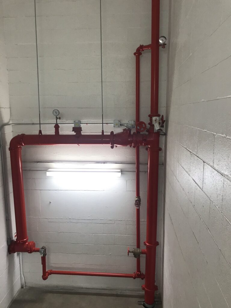
Figure 3: Standpipe with a hose valve, control valve, flow switch, pressure gauge and inspector’s test. A main drain is also routed alongside the standpipe.
For manual standpipes, the fire department pumper truck provides the makeup pressure for the standpipe. The pressure must be 100 psi at the topmost outlet with calculations terminating at the fire department connection. A call to the fire department may be necessary to determine the capability of their pump truck. If the pump truck cannot supply enough pressure to supplement the pressure in the system to get to 100 psi, a fire pump may be required.
Finally, there is the topic of flow. NFPA 14 Section 7.10 addresses the flow rates of standpipes and their hose connections. For Class I and Class III standpipes, minimum flow for the most hydraulically remote standpipe shall be 500 gallons per minute (gpm) through the two most remote 21/2-inch outlets. Minimum flow for additional standpipes shall be 250 gpm per standpipe for floor areas less than or equal to 80,000 square feet.
For a building with at least 80,000 square feet per floor, 500 gpm is required for the second standpipe and 250 gpm for the third standpipe, if required for a nonsprinklered building. A sprinklered building’s maximum flow rate is 1,000 gpm, while a nonsprinklered building’s maximum flow is 1,250 gpm.
The purpose of this discussion is to not only provide some context on all the nuances that come along with specifying a standpipe for a building but also to highlight its importance. Once the height of a building is determined and whether it is sprinkled is understood, the conversation about standpipes should begin.
The more communication among all the interested parties regarding this topic at the beginning of the project, the better. The fire protection engineer, architect, electrical engineer, owner and fire marshal should all be on the same page. This avoids any major setbacks during the construction phase, both in terms of time and resources.

Leslie Cowger, P.E., CPD, CFPS
Published July 11, 2024 in Consulting-Specifying Engineer
Leslie Cowger, PE, CPD, CFPS is a fire protection and plumbing engineer at McClure Engineering.