Maximizing Chiller Plant Design Investment
Pat Travers, P.E. discusses cooling tower limitations for Engineered Systems Magazine.

When constructing a chiller plant, there are several decisions to be made regarding design, equipment selection, and processes. These choices can be influenced by budget constraints and space limitations. However, the paramount consideration is gaining a comprehensive understanding of the intended usage of the plant. Once this understanding is established, it becomes possible to provide recommendations that outline the initial costs and the potential long-term savings over the system’s approximate 30-year life span.
Cooling Tower Placement
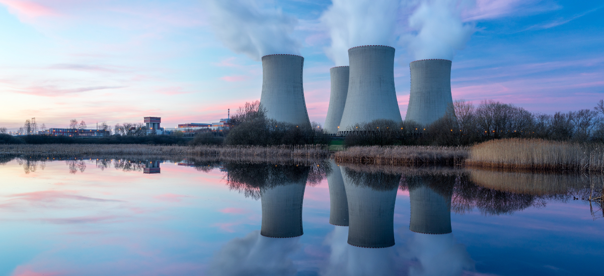
Cooling towers can be located on the roof of or at grade adjacent to the building/cooling plant. A building with a chiller typically has roof area to accommodate a cooling tower. However, in designing central plants, the size of the building roof is often set by the cooling tower footprint and airflow requirements. When locating towers at grade, one has to pay attention to the net positive suction head (NPSH). If the condenser water pumps are in the basement at grade or above grade to allow for piping under the tower, it provides adequate NPSH with normal pipe sizing. If the condenser water pumps are located at grade in the building, then it requires elevating the towers and/or oversizing the pump suction piping to provide adequate NPSH for the pump. Towers located at grade can also have pumps located at the towers to solve the NPSH problem.
A crucial aspect of the decision-making process is closely linked to the physical space and height constraints of the plant. It’s imperative to optimize the utilization of the available area. For instance, if height is limited, it can be entirely reasonable to utilize a multicell tower for a single chiller. Tower height could be limited due to aesthetics, maintenance policies, concerns about height, or cost of platforms. If the footprint is limited, then the tower could be taller. Packaged towers are limited by shipping constraints. Larger applications may require field-erected towers.
One has to pay attention to prevailing winds and possible recirculation of discharge tower air when considering cooling tower locations. Locating at grade in the alley between two six-story buildings is not going to work. When screening for aesthetic requirements, exceed manufacturer recommendations for distances to solid walls or louvered walls.
Piping the Towers
Let’s consider a scenario involving two cooling towers and two chillers all interconnected within the same system. In this situation, the strategy becomes more nuanced. For instance, during spring and fall when one chiller is operational, it’s more efficient to circulate water over both cooling towers to maximize their surface area and decrease required fan power. During the summer, when both chillers are required, both cooling towers are operating at the same speed. If the chillers operate during the winter in cold weather climates, it may be necessary to only operate one cell to prevent icing. In this case, it requires isolation valves on the return water to the top of the towers and a method to equalize the cold water basins. Furthermore, depending on the size of winter heat rejection mode relative to the tower size, it may be necessary to have return water bypass directly to the cold water basin to prevent overcooling even with the fans off.
One can opt for equalizer piping, which is a straightforward method that connects the two water basins to maintain consistent water levels. Alternatively, the towers can be linked by placing a flume between them, allowing water to flow between the two. The most practical approach may be a single chiller and two tower cells, as there’s usually no need to isolate one cooling tower while the other is in operation. This highlights the importance of understanding the operational requirements of the plant.
Properly sizing the equalizer piping is crucial. For instance, to maintain the same water level among three towers when only one is actively receiving water — ideally all the water is drawn equally from all of the basins. This then requires the active tower to flow two-thirds of its water into the equalizer to get to the basins of other cells. The only motive force for this water to flow in the equalizer is by the difference in water heights between basins and should be in the range of ½-inch to 2 inches maximum, but it’s important to consult the tower manufacturer. To achieve this requires low velocity in the equalizer piping.
Insufficiently sized equalizer piping can result in excessive pressure drop, causing the basins of the towers not receiving water to be much lower than the cell receiving the water. Depending on where the water level sensor is located, the cell with the lower water can be at set point, while the cell with the higher water level could be overflowing, wasting water and chemicals. Alternatively, the cell with the higher water level may be at set point, and the cell with the lower water level could be below the ani-vortex baffle, allowing entrained air into the system that can cause a number of problems, such as air binding, pump cavitation, and pipe corrosion.
The alternative approach mentioned earlier involves using a flume. Although this option is a cheaper solution, it isn’t always the simplest solution when compared to using an equalizer. It’s substantially difficulty to install the flume between two towers that are only inches apart when setting with a crane. Placing it between the towers not only presents significant challenges for securing it with bolts due to the limited space but also relies on sealant to ensure everything remains tightly sealed. Repairing and replacing sealant is an ongoing maintenance requirement over the life of the cooling tower. For towers that need to be isolated for maintenance while keeping other cells wet, using a flume blank off plate is more difficult for the maintenance staff. If flume isolation is needed, it needs to be stated when purchasing the tower.
When constructing a chiller plant, there are several decisions to be made regarding design, equipment selection, and processes.
Basin Heating
In cold weather climates, freeze protection is a paramount consideration when designing a chiller plant and cooling tower, particularly in cases where the cooling demand of the building is intermittent. Many designs employ electric immersion heaters within the cooling tower basins and electric heat trace on the piping for this purpose. However, in alignment with an energy-conscious, low-maintenance, and low-cost approach, there’s a heating option that utilizes the system’s piping, taps into the building’s heat source, and features a maintainable heat exchanger and small circulating pump. This heat source can be a condensing boiler or even a geothermal heat pump. A small portion of that available heat is used to maintain the temperature in the cold basin above freezing, circulating it from the condenser water return piping into the cold water basin directly, without running through the fill, and back through the condenser water supply piping. Not only does it provide heat to the basin, but it also heats the exterior piping, eliminating heat trace. The equalizer piping can also only be insulated and not heat traced. However, the location of isolation valves and drain valves require careful placement to avoid trapping cold water that will not circulate and heat by convection.
Despite their popularity and widespread use, immersion heaters have certain disadvantages. The mineral content in the water they heat can lead to calcification, which can adversely affect them and shorten their intended life spans. When a cooling tower design is intended to last 25 to 30 years, it may be wiser to seek a solution that doesn’t require frequent replacement of heating elements. Typically, electric heat trace is part of the electric basin strategy. Electric heat trace historically has not lasted the life of the cooling tower, requiring replacement of the heat trace, reinsulating and rejacketing the piping. This can be a large maintenance expense. However, it should be noted that the same circulation pump arrangement described above could distribute the electric basin heat and keep the piping warm in lieu of electric heat trace, but the extra heat loss needs to be included when sizing the basin heaters. This is where effective communication with the building owner becomes crucial. Presenting options that allow for first cost investments with long-term benefits is consistently valued.
Box Size Versus Horsepower
As mentioned earlier, chillers are highly efficient at their designated task, whereas cooling tower efficiency is directly related to their physical sizes. Cooling tower manufacturers have optimized fan efficiency and fill efficiency for their products. The primary variables for the designer are the size of box, which impacts first cost and the operating horsepower. This, in turn, impacts energy consumption. ASHRAE 90.1 has set minimum limits on tower gpm/fan hp. The cooling tower performance equation is a balance of airflow and wetted surface area. The lower the wetted surface area, the greater the airflow and horsepower becomes to achieve equal performance. However, it’s important to consider the substantial cost difference in running a larger motor over a 30-year period. Sometimes, there’s an opportunity to opt for a larger enclosure size, thus creating more surface area, which can reduce the required fan horsepower and electrical costs. While the larger box size may entail higher upfront costs, the savings over time make it clear these investments pay for themselves in the owner’s payback period and continue to save money over the course of the tower’s lifespan.
Making specific design decisions at the project’s outset can have long-lasting consequences. It’s crucial to grasp these implications and effectively communicate them to the decision-makers. Are the owners inclined to save substantial costs upfront, or would they prefer to realize savings of a multiple of this number over the system’s life span? Providing these financial options in the initial stages is something owners consistently value.

Pat Travers, P.E.
Published January 12, 2024 in Engineered Systems Magazine
Patrick Travers, PE, is a mechanical engineer at McClure Engineering, a mechanical and electrical consulting engineering firm dedicated to the development of innovative solutions to unique engineering problems.


